Make a Wireless Alternative Controller Game

I am making a wireless alternative controller game. In this game, players will control sprites and events in a video game by moving a large, engraved brick. This “brick” will be embedded with a Raspberry Pi 3 B+, an accelerometer, two vibration motors, an inductive charging set, and a LiPo battery. The Raspberry Pi will send data from the accelerometer to a webpage using websockets. The accelerometer data will control the content on the webpage. The webpage is where the players will see the actual video game and the effects of their actions when using the controller. The webpage will send data back to the controller after certain events in the game. This will activate the vibration motors and provide haptic feedback for dramatic effect at key moments.

Although I haven’t fully crafted the story of the game just yet, the main plot centers on a spirit trapped in the brick. The ultimate goal of the game is for the player to release the spirit trapped inside of the brick. The movement of the accelerometer will affect “time” in the game. Players determine the rate at which time moves forward by controlling the movement of the accelerometer. In addition to this, players will need to solve puzzles where they align the x,y, and z axes in a particular manner in order to trigger key plot points. After a series of important events have happened, the spirit will be released from the brick.

In order to create an engaging and believable gaming experience, the controller needs to meet these requirements:

  • It needs to be wireless. I want the controller to look like a stand alone brick and to even feel like one too (so it needs to have a little bit of heft).
  • I want the brick to be completely solid. It can’t have any holes for various plugs/cables. This is why I would like to use a LiPo battery and inductive charging to power the controller.
  • There needs to be minimal lag between the controller and the game happening on the screen. This is why I decided to use websockets and a webserver hosted on the Raspberry Pi.

Here are some materials that I will need for the project:

Progress Thus Far

So far I have connected the accelerometer to the Raspberry Pi and made it send data to a webpage via a websocket. The webpage displays the X,Y, and Z rotation while also showing data for the Pitch, Roll, and Inclination. I’ve added a few visual experiments where I change elements on the webpage according to the incoming data. The thick red line changes hue from bright red to magenta depending on the inclination, while the green rectangle changes location according to rotation of the x-axis. The animated character at the bottom slows down or speeds up according to the rotation of the y axis. At this stage I want to see what kind of transitions and interactions best lend themselves to the incoming data. This will later be used to inspire the puzzle design.

Here is a gif showing the current demo I have on the webpage:
BrickGameDemo2

Game Design/Concept Art
This is a sketch depicting the final design of the brick.

One of the primary concepts of this game is that players can control how time shifts. I would like to divide the screen content into background, midground, and foreground layers which move individually based off of the accelerometer data.

Therefore having individualized control of each layer will amplify this effect as some elements will stay in place while others movie. I think I will use these shifting elements to design puzzles later on, where the player needs to rotate the brick in a certain way in order to align the foreground, midground, and background in order to complete the puzzle and progress onto the next level.

I drafted some concept art which shows the visual direction of the game. I want the visual design to accommodate these shifting layers. Therefore, I opted for a messy collage style which makes room for layering, abstraction, and that will still look aesthetically pleasing during abrupt movement.

What’s Still Left to Do

  • Add the vibration motors to the circuit and make them react to data sent from the webserver.
  • Add inductive charging to the Raspberry Pi
  • Design a puzzle that utilizes the accelerometer data and shifting scenery in the game
  • Build the case for the brick

I’ll work through the remainder of these items over the next couple of weeks!

8 Likes

@jmakivic this is amazing. If I’m not mistaken, this might be the first video game-type balena project log I’ve seen that’s not a server for a video game (e.g. Minecraft).

I’m looking forward to both the next steps and tests of your hardware build, and where the game’s story goes!

gamerpal cc: @lucianbuzzo @cywang117 @mehalter @20k-ultra not sure if you’ve seen this yet. Very cool concept.

3 Likes

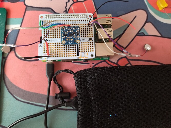
I started soldering the circuit together by placing it all on a Raspberry Pi hat.

I started adding vibration motors and making them vibrate according to data coming from the webpage. Now I need to determine which vibration levels will be felt from inside the brick enclosure and how many motors I would like to include.

VibrationMotor2_1

Think about RPi chipset cooling. Maybe make the brick (one side) from aluminum. If it would work for your plot elements, might be easier if instead of a brick, it were a box. To add weight, use a bigger battery. Add a charge port and a uSD card slot from the outside, so the programming can be customized on your website before download and flash to the user’s uSD card. You could add a heating element, a block of smell/smoke material, and under some circumstances, the “character” inside gets cremated…

@nabutu Thanks for sharing your ideas!

Haha for plot elements it has to be a brick! I think using a bigger battery might not be a bad idea, especially because the Raspberry Pi uses a lot of power. I will not need a charge port from the outside because I plan on using inductive charging to power it.

You raise a good point about the SD card because I plan on this being an installation piece and I will need to know the wifi ssid and password of the venue before I set everything up. Otherwise, I was thinking of getting a wifi dongle or using a hotspot. But, that might get expensive.

@jmakivic you could include balenablocks/wifi-connect in your docker-compose and then the controller can be configured to any future wifi, using the captive portal. :slight_smile:

Thank you @phil-d-wilson that’s good to know!

Building an Inductive Charging Circuit for my Alternative Controller Game

As mentioned in the previous post, my alternative controller game will use a “brick” embedded with a Raspberry Pi 3 B+, a rechargeable battery, and an inductive charging coil. I want to create the illusion that the player is holding a real brick. Therefore the brick-shaped alt-controller has to be seamless and not include any holes for ports or have wires sticking out. This is why I would like the components inside of the controller to be powered by a battery, and then have them be powered using induction charging when the player returns it to a surface.

I’m still in the process of building this inductive charging circuit. Below are a few attempts and experiments at designing this circuit. If there any members of this community who have experience with powering Pi’s via battery and inductive charging, I would love to hear from you if you have any suggestions!

Initial Circuit Design

My initial circuit design consisted of a Raspberry Pi 3, a 1300mAh LiPo battery, and a 5V inductive charging circuit.

The LiPo battery has a voltage of 3.7V while the Raspberry Pi requires an input of 5V.
As a result, the battery couldn’t provide enough power to the Pi, which resulted in a sporadic connection. The red PWR LED light flickered on and off, and the Raspberry Pi was unable to appear online on Balena Cloud.

As a result, the battery couldn’t provide enough power to the Pi, which resulted in a sporadic connection. The red PWR LED light flickered on and off, and the Raspberry Pi was unable to appear online on Balena Cloud.

Using a 9V Battery

I had success powering the Pi with a 9V battery! I added the 9V battery to the inductive charging circuit, and the Pi was able to maintain consistent power even as I connected and disconnected the inductive charging coils.

As a next step, I will try using a rechargeable 9V battery whether it is able to consistently power the Pi. My only concern is that 9V batteries tend to run out of power quickly and that might become an issue when playing the game for long periods at a time.

Using a USB Power Bank

I tried using an Anker USB power bank to power the Raspberry Pi, while taking in current from the inductive charging circuit.

The brick was able to provide consistent power to the Raspberry Pi on its own (as pictured above). However, when I connected the brick to the inductive charging circuit, I realized that it was unable to charge and discharge at the same time.

The inability to charge and discharge is problematic because when the power bank is connected to the inductive charging circuit, all power to the Pi is cut off. I could see this being especially problematic in installation settings where users would keep moving and placing the brick controller on the inductive charging surface, and thus severing the controller’s connection to the digital game.

Exploring Fallbacks/Alternatives

While I’m developing the inductive charging circuit for the controller, I am also exploring alternative options of powering the controller.

The most obvious but least desirable option is to connect a wire to the Pi and power it from main. Gross! It breaks the illusion and ruins the desired aesthetic. Thank you, next. . .

Another more complex option would involve powering the Pi with a beefy power bank and taking it out of the controller’s casing when it runs out. Although a promising option, it raises other challenges. In this scenario, I would have to be able to open the case when necessary, but the case would have to be durable enough to not break open during prolonged periods of user interaction. I’m still a fabrication novice and I’m not sure which approach to take.

This aspect of my alternative controller is still very much a work in progress. I would love to hear from members of this community if you have any advice/solutions on tackling any of the issues described here!

1 Like

I have really enjoyed reading about this project. It is certainly a very imaginative use of Balena and in general wireless technology for human interactions with a game.

It might be worth looking into Dynamo System For USB Charging & Lights. You are facing a very similar issue to charing mobile phones from hub based dynamos when cycle touring. They recommend the use of Buffer Batteries With Pass-Through Charging For Dynamo Hub Systems which could work well here.

Please keep posting updates to this project as it’s an incredible learning resource.

2 Likes

There is so much knowledge here @jmakivic Thanks for sharing. really enjoying these posts

1 Like

Hello @hpgmiskin , thank you so much for your kind words and for your suggestions! This charging system seems like it could be really helpful!

@rahul-thakoor thank you so much!!

Hi @jmakivic, cool project, even cooler documentation! Thanks for your great write up, this will help other people in the future.
I come from a mostly software / web development background, but ended up working on a similar “Raspberry Pi in a brick” project in the past. Here were some of my learnings that I think might apply to your project:

Because a circuit works on a breakboard, doesn’t mean it will work in real life, PCB or proofboard.

Here are some examples of what didn’t work once it went to a small production batch:

  1. Driving anything with a high current draw (LED, motors, etc.) from GPIO. This will cause voltage drops, which will impact sensible sensors (infrared, GPS, etc.) as well as your CPU (kernel panics, reboots, etc.). If you want to use off-the-shelf components, look into motor driver hats. Otherwise, checkout MOSFETs and NPN transistors.
  2. Running 5V LEDs off GPIO. GPIOs are 3.3V, meaning that the HIGH signal only barely makes the cut to a 5V logic circuit. When running through PCB traces, inconsistancies in manufacturing might result in voltage dropping inconsistantly, resulting in LEDs glitching. Use a level-shifter, checkout Adafruit’s guide for explanations
  3. Not following each components datasheet. Most electronics will work without protection on a breadboard. Some resistances and capacitors go a long way. If you can, get a second opinion from someone with experience in electronics to check your circuit before going to production :^)

Use a powerbank.

I looked into building my own LiPo booster circuit, it’s not worth it. As a hobbyist, I accepted that I cannot reach the capacity, efficiency let alone safety of a battery pack. As for induction charging, I found it to be finicky. Depending on the thickness of your casing, placing the device a tiny bit off-center might ruin your charging session. Expose (or extend, preferrably) the USB charging port of your battery, cover it with a flexible plastic cap for aestethics.
Also, think of the fact that your device will be plugged and unplugged repeatedly over a long period. USB-C helps a lot, no more flipping the cable 3 times to get it in. Extending your USB port using a male-to-female cable means when it breaks, you only have to change the cable, not the whole battery. You could even design a battery-pack-hot-swap system, which would allow you to swap an empty battery for a fully charged one in under a minute. To me, this is better than passthrough.

Keep a physical access.

Wireless is great, until it’s not. At the worst moment, WiFi will give up on you or the SD card will die and you will end up empty-handed, with no way to debug your project.
Instead, keep a physical access to both Ethernet port, SD card and USB charging.
If the hardware does not leave your sight, you can secure unwanted access using a simple screw. Otherwise, you’ll have to design something clever enough to keep people out but lets you in!

1 Like

Hi @edorgeville ! Thank you so much for your response and for your kind words!

After spending some more time on this circuit, I think that using a powerbank and allowing for physical access is the best way to go. I agree that nothing I make on my own will be as reliable as a powerbank. Also, it’s best to allow for some sort of physical access because debugging will be nearly impossible otherwise. And yeah, SD cards are absolutely prone to failing, as I’ve starting to realize during this project :sweat_smile:

1 Like

@jmakivic remember when I said you’re rarely the first person to do anything at Balena?

:grin:

It would be interesting to understand what debugging you feel you might need physical access for, and improve the product (if necessary) to solve for that.

You could also talk to @chrisys about the Nano Pi which removes the reliance on SD cards once it’s flashed.

2 Likes

Oh my goodness this is awesome @phil-d-wilson ! It’s just what I’m looking for. Using the magnetic power switch is a really good idea. Although I’m kind of shocked that the LiPo battery was able to supply enough current to the Pi. I definitely had some issues with that, but I’ll try it again.

Hi everyone! Thank you so much for responding to my queries on what to do about my battery situation. I’m still deciding how to approach the power supply situation for my project, but after looking at the responses here and asking around on additional forums, I’ve compiled a list of possible solutions to work towards. I’ve also got some fun graphics and gameplay updates as well!

Here are some ideas on how to address the battery situation.

Adjusting my Original Setup

In my original setup, I was using a 1300mAh 3.7V LiPo battery to power the Raspberry Pi. However, it was not sending enough current to consistently charge the Raspberry Pi. Using this boost converter (PowerBoost 1000 Charger - Rechargeable 5V Lipo USB Boost @ 1A [1000C] : ID 2465 : $19.95 : Adafruit Industries, Unique & fun DIY electronics and kits) would have saved me a lot of grief. It would convert the LiPo battery output to 5.2V and be enough to power the Pi.

Using a Power Bank with Pass-Through Charging

In my previous post, I mentioned that although I could consistently charge the Pi with the USB power bank, I encountered issues when I connected the power bank to the inductive charging circuit because the power bank cannot charge and discharge at the same time. In order to fix this, I could use a pass-through charging power bank. Pass-through charging power banks such as this one( PowerCore Fusion - Anker) can charge and discharge at the same time.

Use a Raspberry Pi that draws less power

Some of my colleagues suggested that powering my controller would be much easier if I just used a Raspberry Pi which drew less power than the Model 3 B+. I could try running my code on a Raspberry Pi Zero or NanoPi. Luckily this is really easy with Balena. I would just have to flash an SD card with the right configuration of Balena OS and upload my code (with possibly some adjustments).

Deciding to Keep the Case “Open”

My original idea involved having the “brick” case be completely sealed with absolutely no holes or ports for wires. However, I am no longer sure if this is still what I want. SD cards are prone to fail, and it’s good to have access to the insides for debugging and changes/upgrades. However, these options provide means of designing a powering system that can stay completely isolated.

Fun graphics update!

Here is a gif of the latest interface for the game. The goal is to use the rotation of the accelerometer’s x,y and z axes in order to align the three elements of the design to the left. I think this sort of interaction will form the basis for the puzzles in the game. The rotation of the axes also affect the framerate of the animations and the speed at which the character moves across the screen. I know that it doesn’t clear the background in certain parts, but kind of like the layered effect it creates. It would fun to play with in a more intentional manner.

1 Like

@jmakivic This is looking amazing and I’m loving the art style. Great work!

1 Like

@cywang117 Thank you!! :blush:

Since my last post, I’ve started building the enclosure for the brick controller. I made the controller by cutting up a shoebox and gluing the sides together. I gave it a front flap so that I could open and access the components inside. I added a layer of gesso to the box and then started to build a clay foam foundation. I sculpted the engraving of the creature trapped inside on the top and added Slavic embroidery patterns on the sides. These “engravings” match moving symbols on the screen and guide the player on how to rotate the controller.

Here are some closeups of the “engravings”:

Next steps for the enclosure include sculpting more symbols on the sides, sanding the clay foam when it completely cures, spray painting a base layer of color and then hand-painting the details.

This basic enclosure for the controller has given me a better sense of what the game-feel will actually be like. This makes it easier to design the interactions and create puzzles based off of movement and axis rotation.

Here is an example of how moving the controller aligns the two symbols to the left. The symbols on the screen match the ones sculpted onto the controller. This provides the player with a hint as to how they are supposed to orient the controller.

At this point, I have a functional controller and a very short game demo. This is a great foundation to start developing a deeper storyline and some more interactions.

I’m currently using a power bank for the Raspberry Pi and have put incorporating inductive charging on the backburner for now. I think my approach to power will evolve as I build different iterations of the enclosure.

As the game gets longer and more complex, I might also have to address issues with lag. Although I am not sure how to approach this yet, the following resources provides some interesting solutions:

http://buildnewgames.com/real-time-multiplayer/

https://www.gabrielgambetta.com/

One approach might be to design the interactions with lag in mind. Perhaps I could utilize the visuals to make the player feel like they are making progress while the lag is occurring. Otherwise, I might add a button to open/close the websockets when it is necessary as opposed to having them continuously send the data from the sensor even when the controller is inactive.