CAD and Fabrication
I’d love to be able to give you an overview of the steps I usually take when trying to design something, but honestly, I can’t. My workflow is usually extremely chaotic, unstructured, and horribly difficult to document.
So, while cleaning up the dozens of AutoCAD files related to this project, I decided to put some structure to the whole thing, and in the meantime create kind of a tutorial of how to not get there again. Maybe you’ll find this useful too.
1. Prepare
Okay, so we have created a BOM, we know what components to use and most importantly why we want to use them. Now it’s time to get familiar with them and understand their physical particularities. (eg. Jetson Nano’s large heatsink). It’s a good idea to just download all the datasheets, and maybe read some of the more important ones. As they say, RTFM !
By the end of each datasheet, you’ll find a dimensional drawing of the part. You basically want to bring the top (or bottom) section of that part into your CAD software of choice. There are a few ways of achieving that:
- Some vendors have downloadable dimensional drawings in a format like DXF (eg. Raspberry Pi)
- Re-draw the section yourself using basic drawing. It might take a while, but you’ll get better at working with your CAD software this way. Plus, you don’t have draw everything. Just focus of the essentials, footprint and mounting methods. (See RPLidar or Jetson Nano in the drawing)
- A hack i’ve learned from my dad
How to copy dimensional drawings from datasheets
- Find datasheet or dimensional drawings in PDF. If needed, isolate the page and save it to another PDF.
I’ll take the Pololu Micro Motors as an example. Luckily, they provide the mechanical drawings as a separate file.
- Look for PDF-to-DWG converters online. I had good results with autodwg and easypdf.
- Open the file in your cad software of choice. Use the scale tool to make sure the dimensions are correct.
Conversion is never perfect, for example text is not always correctly rendered. Still, this is more than usable after it’s scaled to the correct dimension. Feel free to delete details and simplify shapes as much as you can. It’s easier to just delete things than to draw them yourself

So once you have all of your parts in CAD format, create a new drawing file and place them in a configuration like this.
This will become your toolbox, think of them as stencils for what you are going to (virtually) build.
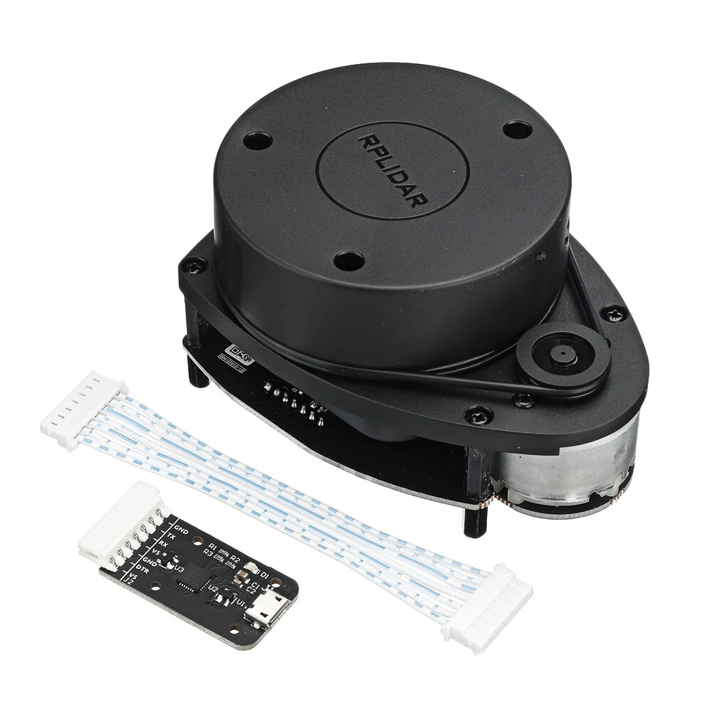
While at it, now it’s a good time to check the weights of your components. In this case, the heaviest that would be the batteries, RPLidar and Jetson Nano. You’ll need that later when placing them.
2. Research
Now is time to think about how you want to fabricate your design. Different fabrication methods require different approaches to bindings and mountings. In more advanced builds, and especially when 3D Printing, it’s crucial to know the properties of the material you’ll be using. For this build, we’ll use laser cutting with 3mm Plexiglas as it’s a cheap and readily available solution almost everywhere.
Laser cutting plexiglas is a two dimensional operation, meaning it cuts trough a sheet of a known thickness. However you can use box joints to mount things at 90 degrees. I use this a lot for in this design for the sensors, and camera mount.
Look for similar solutions
Look for projects that use the same components or that do the same thing. Try to see both the flaws and clever solutions, as you might need them later.
Probably the most important component in this design is the SBC, so I went and looked for solutions designed for the Nvidia Jetson Nano. Here is a list of the official robot kits that support the Nano. Some of them are variations on the same riff, but some designs did stand out:
Waveshare JetBot has some great features. Including a PCB that handles power, motor drivers and even includes battery charging. At 120$ the kit is also extremely affordable. There’s no obstacle detection, no possibility of adding a LIDAR, and no servo to tilt camera. Another disadvantage is it only supports the 4GB Jetson Nano Kit.
Other solutions on that list, seem like a variation of the same idea, but powered by USB Power Banks.
What I really like about the Pololu Romi is the simplicity of he design. Circular shape, differential drive, motors on the center, batteries accessible from underneath, are all features we are going to steal for our design. The only reason I’m not using this platform is that it only supports Raspberry Pi boards. Also, these days availability is not great.
Adding TurtleBot3 to the list has more of an aspirational role than anything else. This platform is on another level . The drivetrain is comprised of two Dynamixel servo motors that enable up to 23kg !! of load. It also features an advanced controller called the OpenCR and Waffle Pi also supports a a robot arm called OpenManipulator. It’s a really serious stuff.
In terms of functionality however, there’s nothing that the TurtleBot can do, and our platform can’t. Ok, apart from lifting 23 kilos. And the robot arm, which costs an additional 1499$.
Ok, we’ve seen enough. Time to get to the real work. This is going to be a lot of trial and error, and probably painful. So get your favorite inspirational quotes about perseverance ready, and let’s go.
3. Fool around. Find out.
Select an outline, in this case a circle, and try to fit the most possible components in the available space.
A few general rules to placing components:
- Draw a line in the middle between your motors, try to distribute all the heavy components along that line.
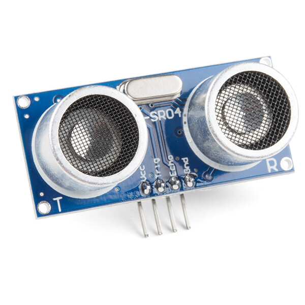
- Be mindful of heat, don’t place components that get hot next to batteries.
- Think about wire management, add holes for wires to go through.
Oh, one more thing, I really recommend this great article about robot dynamics. Actually, that whole website is pure gold.
I won’t show you every step in the process, you either probably know how to do it, or can find much better resources. Instead, I’ll show you some milestones and some highlights.
Attempt 1
Here’s a first attempt, started from a circle, but then extended the shape as I needed more space. Wait, something is missing. Where’s the SBC ?
Attempt 2
Back to the drawing board. This time I decided that instead of extending the shape with a rectangle for more surface, I’d rather just increase the diameter. At this point I also decided I’ll use the Sparkfun Qwiic motor controller due to it’s smaller size. Most of the design decisions in this version made it to the prototype, for example the Jetson cutout, battery positioning, and LIDAR mount.
Attempt 3
One thing about the circular design is that there’s just a few millimeters of clearance between the wheels and the sheet of plexiglas. It’s fairly easy for debris or other little things from the floor to get stuck there and block the motors, that’s why I prefer having the wheels on the outside. So I tried to give the outline a facelift. However, I’ll probably fabricate the round version anyway.
At this point I also added a servo in the front for the camera mount.
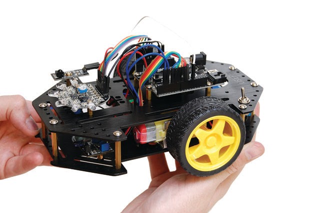
I have no clue how I ended up with this shape, but it might have something to do with this robot platform I used to have some years ago.
Finally…
I realized that the pan servo was useless, as the robot itself needs to rotate anyway to be able to follow an object. Instead I designed a tilt mount for the camera using box joints. I also added mounts for the object detection sensors, and moved the battery holder to the top floor. This way, we have more room for the electronics on the top side, and you can change batteries if you flip the robot.
4. Extrude !
As we are fabricating the platform using laser cutting, this step is totally optional, but I recommend doing it. Mainly because this way you can check how objects fit on the Z axis without having to build anything. For example checking clearance between the Jetson Nano and LIDAR sensor, or seeing if the box joints on the camera mount fit together.
I usually start by extruding the main board along with the screw holes.
For some simple shapes, like the Micro Motors and the brackets, its enough to draw a rough version of the part. However for some other parts, like the Nano, it’s almost impossible, or at least very time consuming.
Grabcad is an incredible resource for 3D files. It’s an immense library of 3D objects. Think GitHub but for CAD. I was lucky enough to find most parts for this build including wheels, brackets, motors, ball caster, Jetson Nano, RPLidar
One of the goals of building a 3D model of the platform was to see how the parts in the camera mount would fit.
And the second one, was to check the clearance between the LIDAR and the heatsink.
A third advantage of having a full 3D model of our robot is that you can import it into Gazebo, ROS’ simulation environment, and have a virtual representation of your robot.
5. Prepare for Fabrication
In the case of laser cutting, there’s very little to do to prepare something for fabrication. FabLabs will usually give you a template file that corresponds to the working surface of their machine. Import it, and try to fit all the parts in that template.
Sometimes, it can happen that you draw a line on top of another line. That usually confuses laser machines and could result in over-burning the material. You’ll need to eliminate those lines. In AutoCAD there’s a command called overkill that does that automatically.
Kerf is the width of material that the process removes as it cuts through the plate. When designing box joints, make sure you remove about 0.1-0.2mm on every side of the “teeth” to compensate for it. If you don’t do that, you’ll probably have to use a file to make the parts fit.
Next up…
we’ll explore the build process, talk a bit about software, and discuss some of the mistakes and fail moments.